2004-2009 Mazda3/MAZDASPEED3
OEM Foot Lamp how-to
by Edwin Man
Copyright
© 2009 Edwin Man. All rights reserved. No
reproduction by any means permitted.
Mazda Japan sells an accessory Foot Lamp kit for the Axela and
markets it only for Japan. Mazda also sold this kit in Canada but
because the kit is exactly the same, the instructions included with the
kit are in
Japanese only.
This how-to is to assist you in making this kit work with a LHD "BK"
Mazda3.
This how-to attempts to follow the Japanese instructions as much as
possible but because of RHD and LHD differences, some adaptations were
made and are shown. If you have a RHD vehicle, please refer to the
Japanese instructions and follow its installation positions.
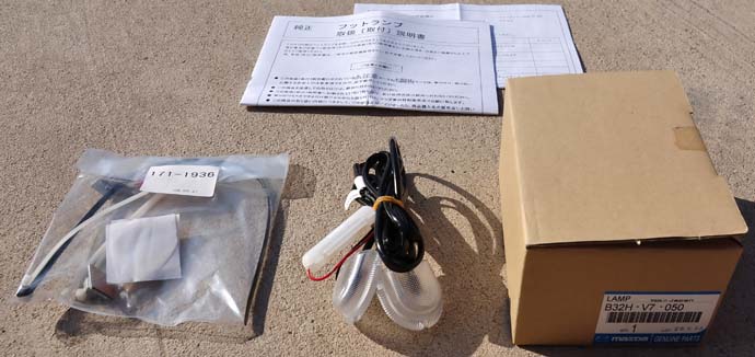
Kit includes:
- Lamp & Harness Assembly (with 2.0 watt bulbs installed)
- 2 double sided tape pads
- 2 self-adhesive wire clip
- 1 large (black) zip tie
- 3 small (white) zip ties
- 2 IDC wire tap
- 1 instruction manual (Japanese only)
- 1 checklist sheet (Japanese only)
Required
time: 1 hour
Difficulty level: moderate
Required tools:
- short P2 JIS crosshead screwdriver
- small flatblade screwdriver
- wire cutter
- pliers
- plastic trim tool
- 10mm wrench
- alcohol pads
- good quality commerical grade black electrical tape (ie: 3M
Super 33+)
Basic disclaimer: work carefully and take your time.
If you screw
up, it's your fault. Always exercise caution when working around
electrical systems.
Parts Removal
- Record all radio presets and
settings. Open the hood and
disconnect the battery using a 10mm wrench. You will have to remove the
battery cover by
pressing on the clips where the air scoop duct meets the battery cover.
- Remove the driver side scuff plate.
You can easily remove it
by grabbing onto the edge where it is over the carpet and gently
pulling it off.
- Remove the driver side kick panels.
There is one by the door and
one by the pedals. Both kick panels are held in place by a plastic push
pin. The push pin is removed by pulling the center portion out then
prying the outer portion out. Pull it towards the rear
of the vehicle to remove the kick panel.
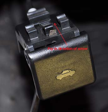
- Remove the hood opener handle. Pull
the handle towards you then use
a flatblade screwdriver and insert it into the slot in the middle. Pry
the screwdriver towards you as you pull the handle off.
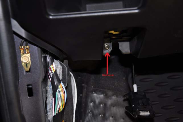
- Remove driver side lower dashboard
panel. There is a phillips
screw that was once covered by the hood opener. Remove this screw then
pull the panel off. The rest of the trim panel is clipped onto the
dashboard. You may need to pull the weather strip back to get the panel
off easier.
- Disconnect the dimmer switch,
headlight leveling switch (if
equipped), passenger side airbag off switch (if equipped), and DSC
switch (if equipped).
- Remove the OBD-II diagnostic port
by prying against the clip at the
ends of the connector as shown below.
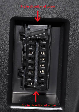
Once the diagnostic port has been removed, the lower dash panel can be
taken out of the car. Set it aside in a safe place where it will not
get scratched.
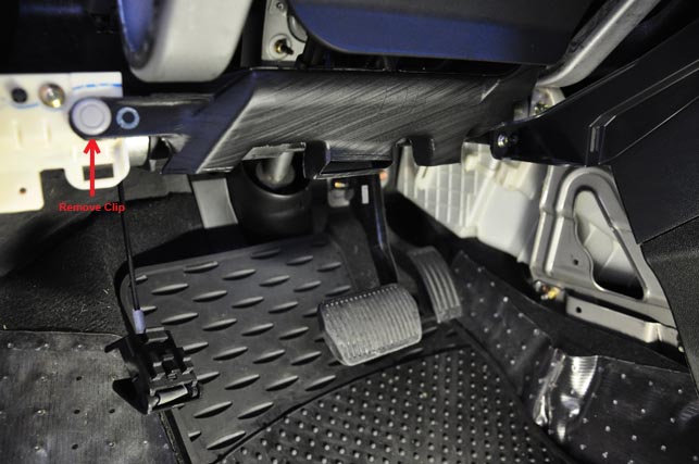
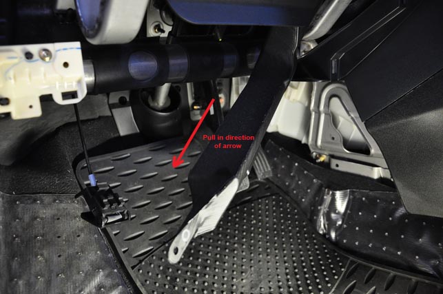
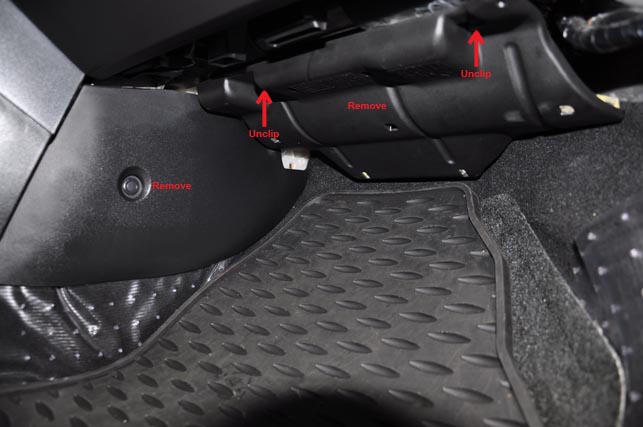
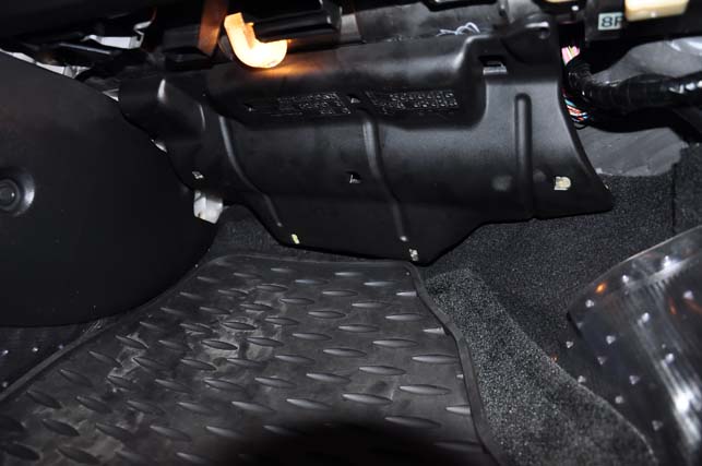
- Remove the lower heater duct as
shown below.
- Remove front passenger scuff plate
and kick panels. There
is one by the door and one by the exhaust tunnel. Both kick
panels are held in place by a plastic push pin. The push
pin is removed by pulling the center portion out then prying the outer
portion out. Pull it towards the rear
of the vehicle to remove the kick panel.
- Remove the plastic cover under
dashboard below where
the glove
compartment is. Push against the clips shown below then just grab it at
the edges and gently yank it off.
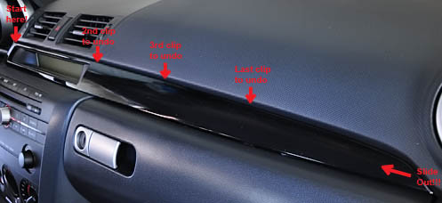
- Remove the dashboard "decoration
panel".
Using your plastic trim tool, start at the center dashboard end of the
strip and pry it off and work across to the right side of the LCD
display and unclip that end. Work slowly across to the passenger side
of the dashboard until you get to the pointed end of the "decoration
panel". The very end is not clipped on but is just hooked onto the
dashboard. Pull it out towards you at a slight angle then it will slide
off in the direction towards the driver side.
- Pull back the weatherstrip along
side the dashboard up until the
bottom of the "A" pillar (top of the dashboard).
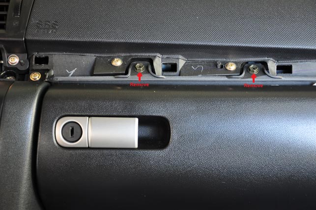
- Remove the glovebox by removing the
black 8mm hex/phillips screws
shown below and pulling the entire glovebox assembly out towards you.
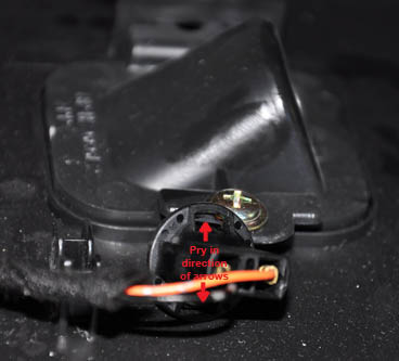
- Remove the glovebox light by using
a small screwdriver to pry the
light bulb socket clips outwards as shown below.
You should now have the passenger side of the dashboard apart.
Parts Installation
- Remove the light housing from the
longer side of the
foot lamp harness by squeezing the cover and pulling it off. The bulb
holder/harness will just slide off the back side of the housing.
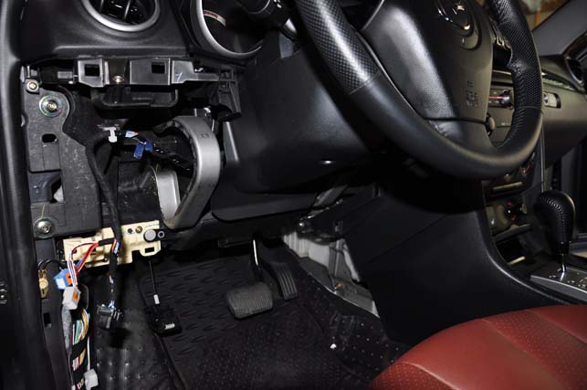
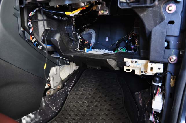
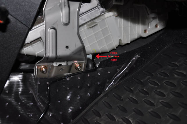
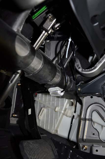
- Feed the longer bulb harness (of
which you just taken apart) to the
driver side under the HVAC unit as shown below. The harness will run
above the shifter cable gromet.
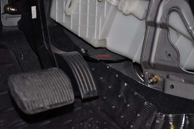
- Pull the harness (you just fed) out
by the accelerator pedal.
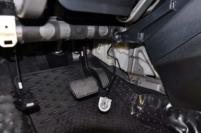
- Reinstall the lamp housing to the
driver side harness then route
the harness as shown below.
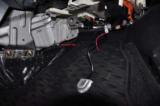
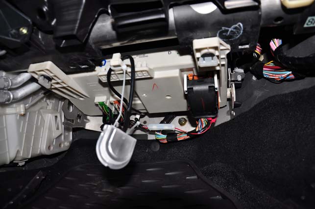
- Clean the back side of the driver
side light housing with an
alcohol pad then apply the double sided tape onto it.
- Using the same alcohol pad, clean
the bottom of the dashboard frame
and HVAC unit then affix the light housing and harness clip as shown
below. Route the excess harness upwards towards the harness near the
steering column and use the small (white) zip tie to secure it as shown
below. Secure the harness onto the harness clip against the HVAC unit
also as shown below.
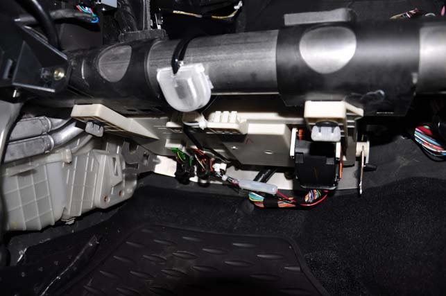
- Route the passenger side harness
bundle around the outside of the
power junction box (PJB) and above the metal bracket as shown below.
- Feed the passenger side harness
bundle through the space between
the PJB and the firewall down towards the floor as shown below.
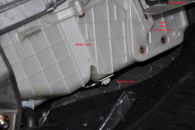
- Pull excess harness from driver
side and with an
alcohol pad
clean the bottom of the HVAC unit then attach harness clip as shown
below. Route the remaining harness from there below the HVAC unit to
the firewall then upwards a few inches before it will go towards the
PJB. This will ensure it will not interfere with cabin filter
removal/installation.
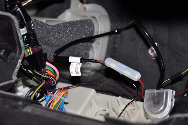
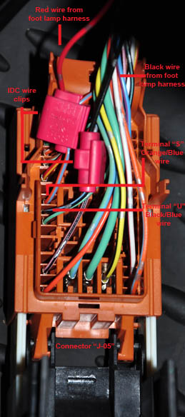
- Locate harness connector "J-05" and
disconnect it. Flip the large
black handle towards you to disconnect it. Connector "J-05" should be
the sole large harness connector located at the bottom side of the PJB
(the side without the fuses).
- Locate terminals "U" and "S" on
harness connector "J-05". The wire
colors should be Black/Blue for terminal "U", and Orange/Blue for
terminal "S". The colors and terminal positions are the same regardless
of RHD or LHD vehicle.
- Connect the RED wire of
the foot lamp harness to the Orange/Blue wire using the supplied IDC
wire clip. Connect the BLACK
wire of the foot lamp harness to the Black/Blue wire using the supplied
IDC wire clip. There are two slots on the IDC, one is a pass-through
side and the other has a stopper. Feed the foot lamp harness wires to
the stopper side and the vehicle harness wires to the pass-through
side. Once the wires are in position, squeeze the metal portion of the
IDC to puncture and secure the wires with a pair of pliers. Double
check to make sure the wires have been successfully punctured through
and are secured in place by the IDC. If everything looks good, secure
the IDC by folding over the plastic tab and then clip it into place by
squeezing it with a pair of pliers.
- Wrap the IDCs and wires a few
millimeters before it with electrical
tape.
- Reconnect harness connector "J-05"
to the PJB. Connector
MUST be seated flush with the
socket on the power junction box!
- Secure the remaining foot lamp
harness with the two remaining small
(white) zip ties as shown below.
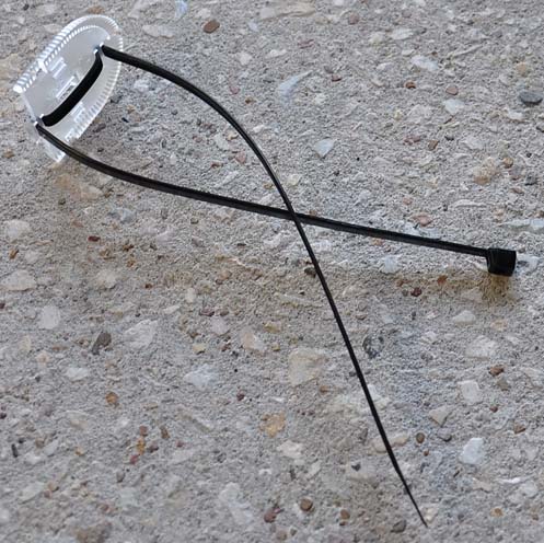
- Remove the light housing from the
foot lamp harness by squeezing the cover and pulling it off. The bulb
holder/harness will just slide off the back side of the housing.
- Insert the long (black) zip tie
through the light housing back as
shown. Ensure that there is only 30mm length between the housing and
the head (clip end) of the zip tie! The center portion of zip tie MUST
route against the flat side of the light housing!
- Reinstall the lamp harness to the
light housing.
- Remove the passenger side lower
heater duct the same way you did
with the driver side.
- Clean the back side of the light
housing with an alcohol pad and
then apply the remaining double sided tape to it.
- Loop the light housing and harness
above/around the dashboard frame
through the space between the PJB and dashboard frame.
- Temporarily reinstall the lower
heater duct and at the same time
test fit the light housing in the space below it in order to understand
its approximate install location. The light housing will be installed
in an angle facing towards you. Failure to install the light housing at
an angle results in interfering with the lower dashboard panel
installation!
- Remove the lower heater duct again
then clean the portion of the
dashboard frame in order to affix the light housing to it. Install the
zip tie on the light housing to secure its final location. Trim excess
zip tie off.
- Reinstall the passenger side lower
heater duct. You may
have to adjust the light housing's position a bit in order to get the
duct to fit properly.

- Trim excess zip ties off on both
sides of the car.
- Reinstall the glovebox in reverse
order of removal. Take note that
the glovebox light's harness is secured on top of the glovebox unit
with a placeholder near the light. Position the yellow part of the
harness to that spot.
- Reinstall the passenger side
weatherstrip.
- Reinstall both passenger side kick
panels and scuff plate in
reverse order of removal.
- Reconnect the dimmer switch,
headlight leveling switch (if
equipped), passenger side airbag off switch (if equipped), and DSC
switch (if equipped) that are on the lower dashboard
panel.
- Reinstall the OBD-II diagnostic
port into the lower dashboard panel
by simply clipping it into place through the hole.
- Reinstall driver side lower
dashboard panel in reverse order of
removal.
- Reinstall hood opener handle by
sliding it through the slots and
clipping it into position.
- Reinstall the driver side weather
strip if necessary.
- Reinstall both driver side kick
panels and scuff plate in reverse
order of removal.
- Reconnect the battery and reinstall
the battery cover.
- Your foot lamps should now be like
this:
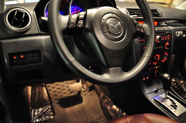
The foot lamps will operate through the dome light circuit. They will
come on even if the dome light is in the "OFF" position. They will not
come on without the doors being opened even if the dome light is in the
"ON" position. This is due to wiring circuit design and a workaround to
this problem involves high technicalities.
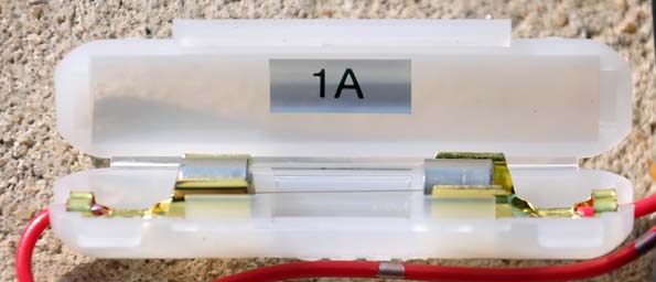
Notes
A replacement fuse should be a 1 amp glass fuse as shown.
Alternate installation:
I have found that the harness routing on the passenger side as
instructed by the Mazda instructions causes PJB removal difficulties.
The solution to this is to route the harness above
the PJB instead of below it. The harness will still be zip tied to the
tab at the front of the PJB. You may choose to use a releasable
(reusable) zip tie in lieu of a normal zip tie to aid future PJB
removal/installation. PJB removal is a necessary matter during cabin
filter changing.