2001-2003 Protegé Foot Lamp how-to (for keyless
entry
models)
by Edwin Man
Copyright
© 2007 Edwin Man. All rights reserved. No
reproduction by any means permitted.
Mazda Japan sells an accessory Foot Lamp kit for the Familia and
markets it only for Japan. Unfortunately Mazda never sold such a kit
overseas and therefore the instructions included with the kit are in
Japanese only.
This how-to is to assist you in making this kit work with a LHD vehicle.
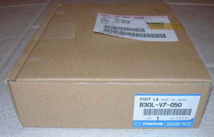
This how-to is for the B30L-V7-050
kit, which is for vehicles with keyless entry equiped. Vehicles without
keyless entry require the B30K-V7-050 kit which includes a light
control module for delayed delumination. Since I do not have the
latter, this how-to will not cover that.
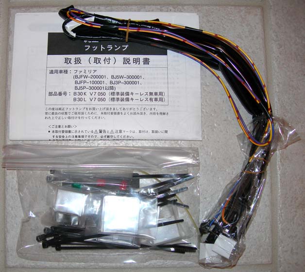
Kit includes:
- Wiring harness (with 1.4 watt bulbs installed)
- 2 orange bulb filter covers
- 2 green bulb filter covers
- 1 large (yellow) zip tie
- 13 small (black) zip ties
- 1 small double sided tape
- 1 large double sided tape
- 4 cloth tapes
- 1 instruction manual (Japanese only)
Required time: 35 minutes
Difficulty level: moderate
Required tools:
- short P2 JIS crosshead screwdriver
- small flatblade screwdriver
- wire cutter
- pliers
- alcohol pads
Basic disclaimer: work carefully and take your time.
If you screw
up, it's your fault. Always excercise caution when working around
electrical systems.
1. Record all radio presets and settings. Open the hood and
disconnect
the battery.
2. Remove the floor vent kick panels. They are the ones where the
exhaust tunnel is.
3. Remove the gauge cluster.
4. Remove the trim below the steering column.
5. Install the bulb filter covers onto the bulb. The kit includes green
and orange ones for you to choose.
6. Feed the foot lamp wiring harness to the passenger side of the car
from the driver's side through the area where you removed the floor
vent kick panels. The harness will run in front of where the center
console ends.
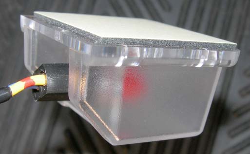
7. Assembly one light housing fixture and attach one side of the square
double sided tape as shown. Be sure to clean the surface with the
alcohol wipe before attaching the tape to ensure proper adhension.
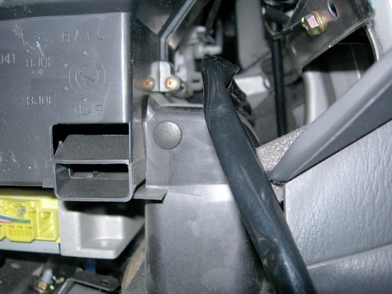
8. Attach assembled light housing fixture to the bottom of the
evaporator box as shown. Attach wiring harness to the bottom of the
evaporator box as shown. Be sure to clean the surface with
the alcohol wipe before attaching the tape to ensure proper adhension.
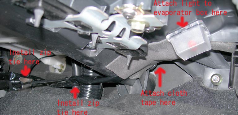
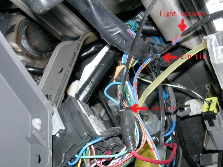
9. Attach other portions of the passenger side section of the wiring
harness with zip ties as shown in above picture and picture below.
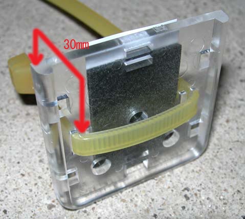
10. Prepare driver's side light housing fixture by inserting the large
yellow zip tie into the base as shown. Be sure to leave only 30mm from
the base to the zip tie head as shown. Once proper length is
determined, fold zip tie so that it would be as flat as possible when
it is in its installed position.
11. Attach light housing fixture base to steering shaft as shown. Be
sure to clean the surface with the alcohol wipe before attaching the
tape to ensure proper adhension.
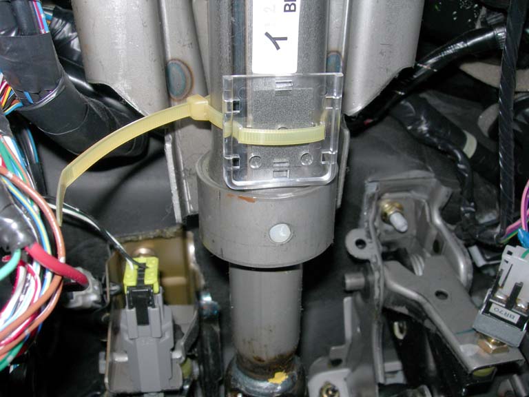
12. Attach light housing fixture onto base.
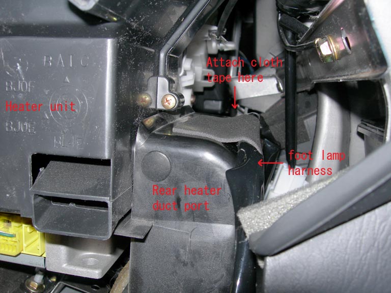
13. Attach foot lamp wiring harness with cloth tape to the heater duct
behind the ash tray area as shown.
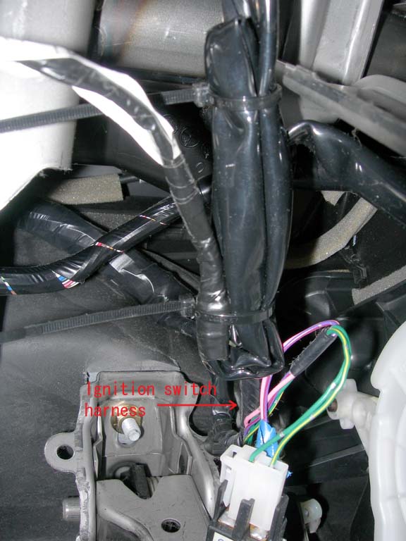
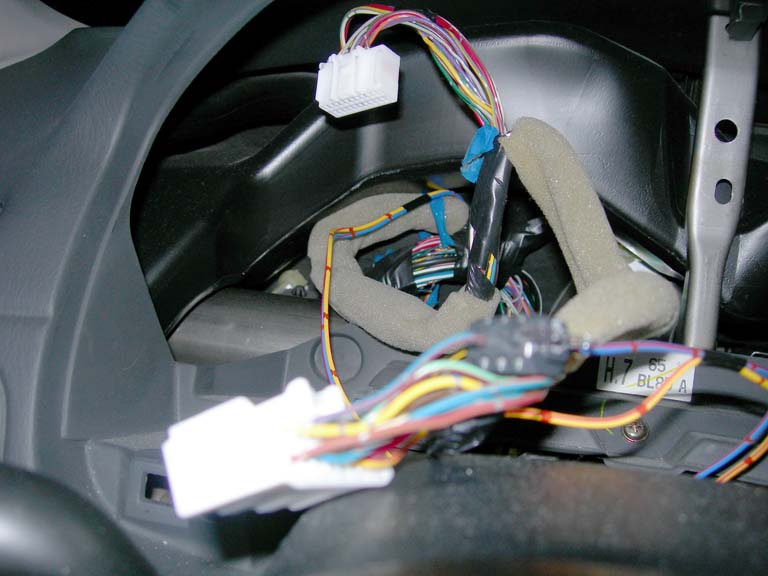
14. Bundle excess harness and zip tie it together onto the ignition
switch harness. You will find this small harness by following the
steering column trim where the key hole is.
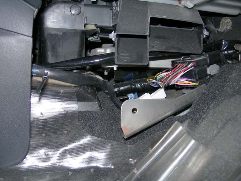
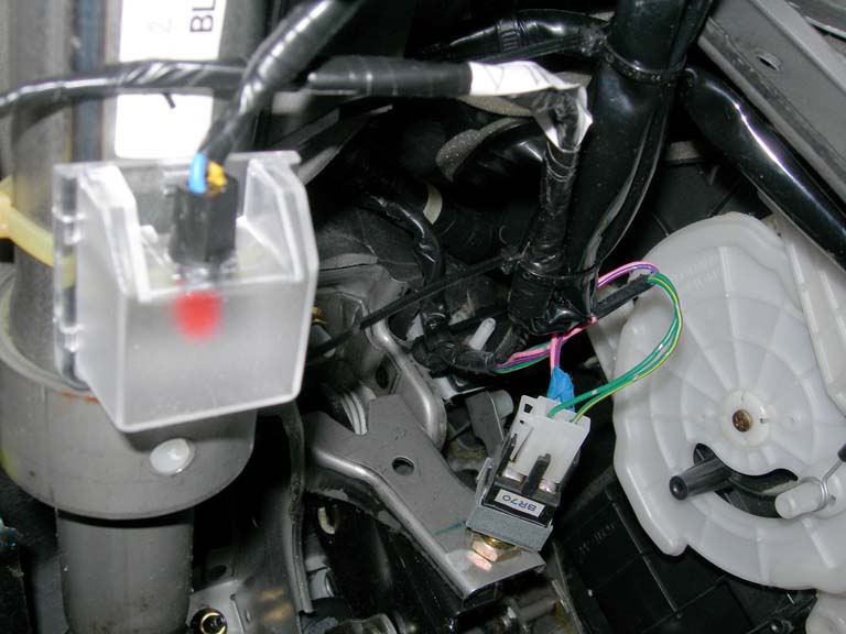
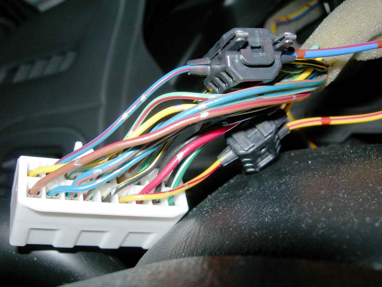
15. Attach power source end of foot lamp wiring harness to dashboard
wiring harness as shown.
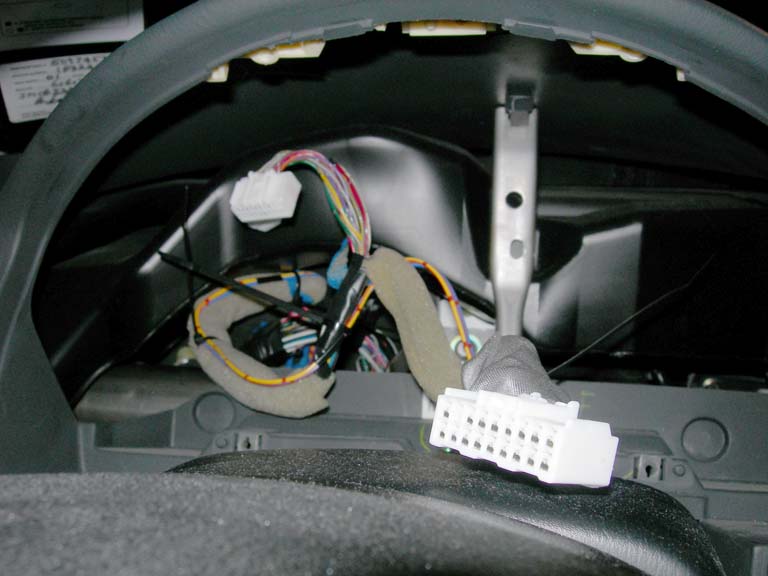
16. Feed foot lamp wiring harness to gauge cluster area. Route wires to
location as shown.
17. Locate Blue/Red wire on large gauge cluster connector (Pin 1O) and
Yellow/Red wire on large gauge cluster connector (Pin 1H). Attach
corresponding wire taps to the wires by closing the tap and squeezing
them with a pair of pliers.
18. Wrap wire taps with one piece of cloth tape then zip tie foot lamp
wiring harness to gauge cluster wiring harness along four points.
19. Cut off all excess portions of zip ties.
20. Reconnect gauge cluster but do not reinstall it yet.
21. Reconnect battery.
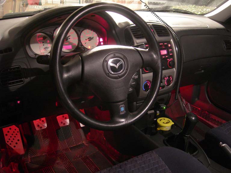
22. Ensure dome light and foot lamps are operational. Check delayed
entry operation by closing all doors. Lights should slowly dim until
they are off.
23. Reinstall all removed parts.
24. Your foot lamps should now be like this: